4. Hadron Imaging
My research focuses on a new medical hadron imaging setup. This section goes into detail on some of the other approaches to hadron imaging that are currently conducted. At the end of the chapter our approach will be briefly summarized and compared to the competition. The next chapter will treat our setup at length.
4.1. Nuclear Emulsion Film Detection
The oldest method of proton imaging (Koehler, 1968) is still of interest to some. Cost and ease of use are cited as advantages. Braccini et al. (2010) proposes a setup where a “brick” of interleaved absorbers and nuclear emulsion film is used to obtain an image, akin to a sampling calorimeter found in some high energy physics experiments. The brick is made up of two parts: first the proton will go through 30 emulsive sheets interleaved with 1.5mm thick absorber plates. Second the proton goes across 0.5mm absorbers interleaved with 40 emulsive plates. The beam will be tune to deposit the Bragg peak in the second part, which has increased precision compared to the first.
Figure 1: Reconstructed image of a stepped PMMA block. A clear distinction between the 1 and 4cm thickness can be made. (Braccini et al., 2010)
Figure 2: Reconstructed image of the PMMA block with aluminum rods. (Braccini et al., 2010)
The paper describes the Monte Carlo simulation of the setup and the results of a test run at the Paul Scherrer Institute in Switzerland.  protons per
  are required for a complete image, and a low intensity beam is used to spot-scan the object. Two phantoms are scanned: an object of homogeneous substance (PMMA) with a thickness of 4cm on one side and 1cm on the other. The second object is made up of a block of the same material but with five embedded aluminum rods.
While this particular research appears to be in its initial stages, the reconstructed images in figure 1 and figure 2 are convincing. However, no numbers for position or energy resolution are provided.
4.2. Strip Detectors
Another detection paradigm found in high energy physics is the strip detector. Johnson et al. (2003) consider their use for proton imaging. Four plates with 400μm thick silicon strip detectors (SSDs) are used for both tracking and calorimetry. Two groups of two plates at an angle of 90 degrees are placed some space apart to provide two points for the track. One 2-plate plane is placed directly after the phantom and the other 25cm farther away. The time over threshold (TOT) of a signal in a strip is used to give energy loss information. Given the known dimensions and composition of the strip, there is a correlation between deposited charge and signal, although the resolution is not quite as high as dedicated calorimeters.
The setup is put to an experimental test, as well as simulated using Geant. A phantom consisting of a hollow aluminium cylinder is successfully imaged (figure 3). It is noted that the group of SSD plates farthest removed from the phantom provides no discernible features of the cylinder, and was therefore not used. A cross-section of the cylinder at its widest is used to obtain some more specifics of the measurement. The number of proton events per pixel varies from approximately 100 to 500, owing to the non-uniformity of the beam. Around the edges of the aluminium the reconstructed image is fuzzier than the Monte Carlo of the setup written with Geant4. This discrepancy is attributed to both a calibration accuracy of 15% in the energy conversion electronics, to multiple Coulomb scattering of the protons (although the simulation takes this into account), and divergence of the degraded proton beam. A more specialized simulation of the energy distribution of the proton beam indeed shows a larger deviation (RMS) around the interfaces between air and aluminium. The flat response of the plates farthest away is also attributed to the multiple scattering. Although both energies are found in the data, they appear nearly fully decoupled from position.
Figure 3: Reconstructed aluminium cylinder using silicon strip detectors for both tracking and calorimetry (Johnson et al., 2003).
To improve the position resolution, cuts on exit angles are recommended. Johnson et al. (2003) ends with the remark that their setup gives an energy resolution of approximately 20%, “which could mean that the image contrast at acceptable dose levels is insufficient”. Exploring different techniques for the measurement of energy is recommended and even promised.
4.3. Strip Detectors and separate Calorimeter
Much research on hadron imaging is conducted in Italy, often in the context of the PRIMA collaboration. Talamonti et al. (2010) describe a similar setup as in the previous section, but this time coupled with a separate calorimeter to improve the energy resolution drastically. The calorimeter used was made up of a CsI crystal attached to a PMT. This group uses four strip detector planes, again each made of two strip-plates at an angle of 90 degrees from each other. Two planes were placed just before and after the phantom, and two between a bit farther up- and downstream. This setup was built to be able to cope with a proton beam frequency of 1MHz.
In addition two phantoms are tested. Both are complex compared to the ones used in the previously mentioned studies, and consist of different materials and complex shapes suitable to a detailed study of detector performance. Phantom “A” is a block of PMMA with holes of varying radius, while phantom “B” is more complex, with finer structures and composed of a large variety of materials. The spatial coordinates obtained with the four planes are used as input for a most likely path (MLP) fit, for which a method proposed by Williams (2004) and verified by Cirrone et al. (2007) was used.
Again the detection plane farthest removed from the phantom shows very little detail. The four planes coupled with the MLP track reconstruction method did however recover some of the detail present in phantom “A”, indicating the MLP method is able to mitigate some multiple scattering. With phantom “B” it becomes clear that the setup is not sensitive to small features yet: a spatial resolution of 1.1mm is calculated. The energy resolution is put at 4%, and among the limiting factors “the number of proton histories” is mentioned. Not enough tracks have been recorded, so the statistics couldn’t be better than this.
In a paper published earlier the same year, Cirrone et al. (2007) uses a similar setup with YAP:Ce and YAG:Ce calorimeters. Energy resolutions of 3% and 2.7% are found, respectively. Although the paper concludes that further studies will be carried out with the YAG:Ce calorimeter, it is not explained in the following paper on what basis another, third option is chosen.
Civinini et al. (2010) also combines strip detectors and a calorimeter. This time a YAG:Ce crystal is used, and a silicon strip thickness of 200μm is mentioned to be a good compromise between scattering and detection efficiency. The energy resolution of the calorimeter is claimed to be about 1%.
4.4. GEMs and Sampled Silicon Calorimeter
Project AQUA, an initiative that tries to advance the research on hadron therapy, makes use another kind of setup, named PRR10 (Amaldi et al., 2011). This group uses a pair of Gas Electron Multipliers to track protons and a stack of thin silicon plates to measure the range and therefore energy of the proton (figure 4). The whole device is rather compact, and the stated purpose is real-time imaging with sub mm accuracy and a range accuracy of a “few” percent, using protons per image. Currently the data acquisition for the GEMs was limited at 10kHz, but an improved system managing 1MHz is foreseen. Quite a few lines are spent on the data acquisition, and the online and automated calibration is an impressive achievement.
Two phantoms are investigated. The first a relatively simple one, a slab of plexiglass from which some cylinders of varying length and radius are removed, resulting in the left pane in figure 5. The second phantom is constructed so as to be more similar to the more homegeneous composition of the human body. It consists of three plexiglass cylinders with varying radius immersed in a volume of water. Its reconstruction is found in the right pane of figure 5.
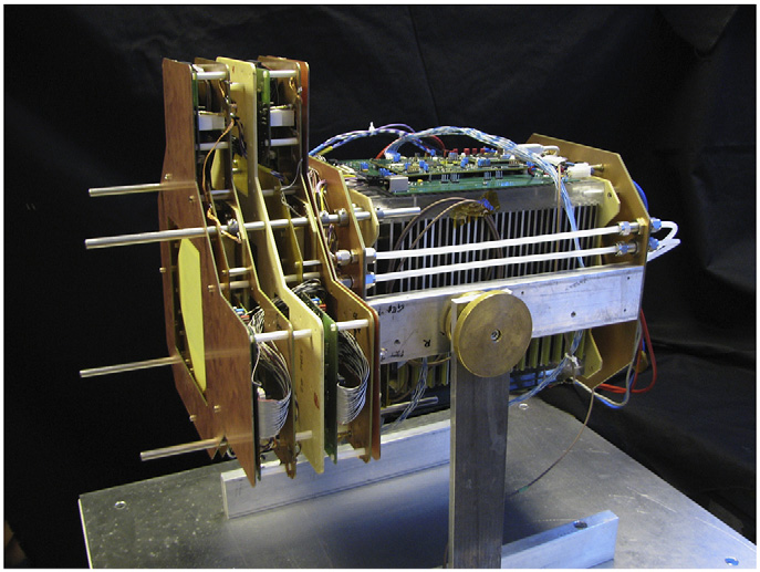
Figure 4: Photo of the segmented Aqua setup. (Amaldi et al., 2011)
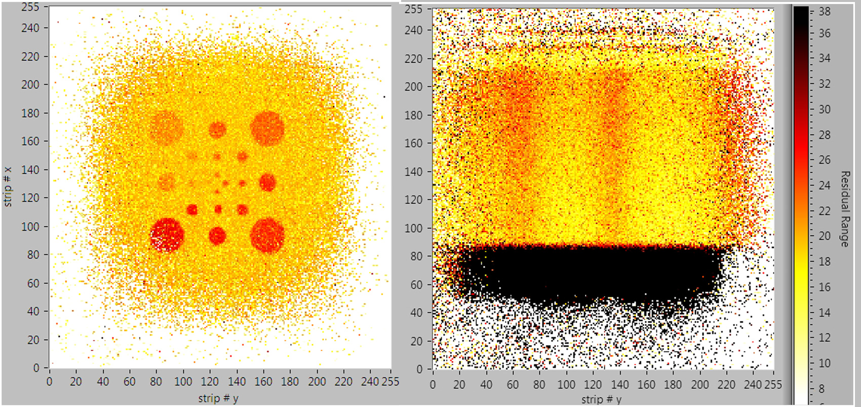
Figure 5: On the left, an AQUA reconstruction of a slab of plexiglass with some cylinders of varying length and radius removed. Right: a reconstruction of three plexiglass cylinders with varying radius immersed in a volume of water. (Amaldi et al., 2011)
The spread in proton beam spot introduced by copper diffusers is specifically mentioned as an important point of improvement for clinical setups. Active raster scanning methods should improve the energy resolution. Results were obtained and analyzed on-line, and compared to a Monte Carlo off-line. The claimed theoretical accuracies are obtained, although the energy resolution is not elaborated upon further. The paper concludes with one remark in particular, namely that the GEMs prove to be a cheap, low weight alternative to traditional silicon strips and can easily be increased in size.
4.5. Scattered Events Beam Reconstruction
With the argument that objects in the beam scatter beam particles and generate secondary ions, Jakubek et al. (2012) in Prague propose a detector placed outside the beam to capture some of these stragglers. The problem of scattering is turned into a detection mechanism, because at the interface of materials with different densities, there is an increase in scattering. Using a stack of 2D silicon detection grids, TimePix chips, a 3D tracker is made. It is proposed that with such a setup the whole beam line can be imaged (figure 6), primarily to use for real-time beam verification. An energy measurement is not reliable since energy information is often lost in the scattering. Henriquet et al. (2012) suggest that therapy with heavier ions might be monitored with a scatter detector, because heavier ions generate secondary protons especially at the interface between bone and other tissue.
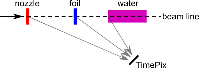
Figure 6: The TimePix chip stack records stragglers, predominantly originating from interfaces between materials.
4.6. The Nikhef/KVI approach
From the examples seen above we can conclude that medical hadron imaging is in its early stages. Most approaches are not ready for practical medical use. This means that the recent start at Nikhef for a hadron imager is not a tremendous disadvantage. Currently the purpose for the setup is to lead to a clinical device for use in a future proton treatment facility in Groningen, where the KVI is closely involved. To circumvent the conversion from Hounsfield number to proton stopping power, a proton image is desired. A feasible time schedule for a single treated patient session is about 30 minutes, of which the total treatment time is about 2 minutes. Similarly, imaging should take up not more than 2 minutes to be practical, and would be a last check on the morphology of the patient. It will depend on the final design if the treatment plan allows for last minute adjustments: in the case of passive beam shaping, the construction of a new bolus would mean that treatment must be postponed. Considering how large a typical tumor can be, let’s say 10cm cubed, the viewing window, or detector size, should be of similar size. That said, our current setup has a GridPix tracker and a  calorimeter.
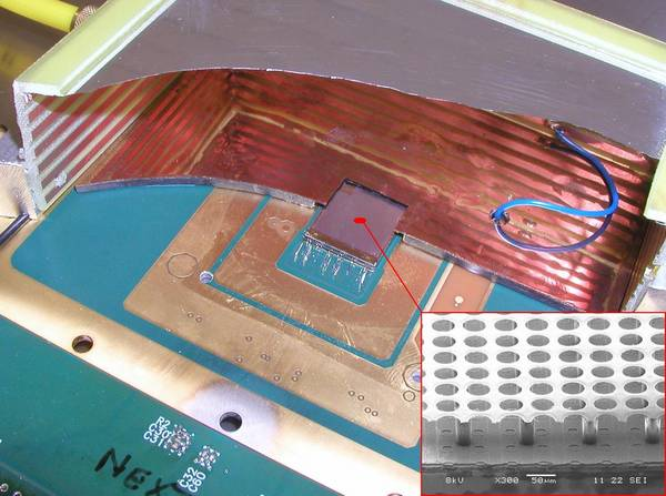
Figure 7: A GridPix cut-away view. In the center is the chip, surrounded by a drift cage, containing the drift gas. The inset shows a magnified view of the Ingrid on top of the TimePix chip. The drift cage used in our setup was smaller than what is shown here: at first 1.5cm cubed and later replaced with a 4 by 4 by 1.5  volume.
- The GridPix consists of a small gas container attached to a GridPix chip. The GridPix chip is a TimePix chip, with the addition of an Ingrid. An Ingrid is a 1 μm thin perforated aluminium foil suspended 50 to 75 μm above the silicon by a nonconductive spacer (figure 7). Two HV potentials are applied, one between the top of the drift cage and the grid, and the other between the grid and the chip, which is grounded. The gas container volume above the grid function as a drift volume, where ionizing particles will break up gas molecules into ions and electrons (Sauli, 1977). These will drift because of the potential. When electrons arrive at the grid, they enter the avalanche region. Between the grid and the chip the field is kept at
 , which causes the electrons to accelerate. As their speed increases, so does the chance of ionizing gas particles and so freeing more electrons. This multiplication effect results in an avalanche of electrons directed towards the chip. This amplified charge then induces a charge in the chip, which is then registered as a hit. The TimePix chip consists of 256x256 pixels, each 55 μm squared. Each pixel is able to measure the Time of Arrival, which means that given a certain shutter signal, it can measure the time between the start of the shutter and the time of the event (for each pixel). Given a known drift velocity, the ToA for each pixel can be converted to a height and a 3D image of a passing charged particle can be reconstructed. The chip is digitally connected to a standard computer, where Pixelman and RelaxDAQ software are used to configure, calibrate and read out the chip. More detail on GridPix and TimePix may be found in Tsopelas (2011), but the main advantage over SSDs is that gas scatters much less than silicon.
 - The calorimeter is much simpler, and consists of a PMT attached to a crystal, that generates an amount of light with a proportional relation to the absorbed energy of an incoming charged particle. The PMT registers this light, after which an ADC converts it to a digital signal. We use an ADC borrowed from the HiSparc project, which is a small box with a two channel 400MHz sampler, connected to a computer via USB.
- The trigger system is built with scintillators roughly the size of a side of the drift cube. This fast scintillating material ensures as little delay as possible. The trigger logic is constructed such that the tracker and calorimeter operate in acquisition mode by default. A signal from the trigger system stops the measurement, writes data to the computer, and resumes acquisition. This way we hope to achieve as little dead time as possible. In a future iteration the particle accelerator itself may provide the trigger.
Typical considerations for the eventual use of the setup are:
- How many protons do we need for an image?
- What is the event acquisition rate that is required?
- How large is the beam spot?
- What is the required beam current?
- How many tracks can be correlated (before and after patient)?
- Scattering in strip detectors versus GridPix: is GridPix advantageous?
These points are interdependent to a certain extent, but it is still informative to see what are key points to think about when constructing the setup. As for size we are not quite there yet: our drift volume and therefore viewing window is 1.5cm squared. Our aim is to accommodate the desired clinical use case as optimal as possible. In the next chapter more detail will be given on the detectors, in particular some of the current deficiencies and attempts at improvement. Data obtained from test runs at the KVI accelerator and from laboratory sources are discussed to demonstrate the performance.