3. From High Energy Physics to Medicine
Since the Renaissance the development and use of tools in the natural sciences have allowed our species to conduct research further and further beyond the limits of our biological perceptions. These tools often proved interesting subjects of research themselves, and have spun off many useful and presently completely commonplace inventions. Such research has involved the construction of ever larger and better detectors. Legend has it that an apple caused Newton to derive the fundamental laws of motion, and in the age of Rutherford the atomic nucleus was discovered using a tabletop setup. Current forays into fundamental science require tools that range in size from the church-sized Atlas detector in Geneva to the 3000 square kilometer Pierre Auger observatory in Argentina. Early particle detection often was based on photographic film and the measurement of heat. Nowadays there are many kinds of detection methods like silicon chips, scintillating crystals, sampling calorimeters, and computers combining millions of data channels to describe a single event.
These devices are known for their use in the fundamental study of matter, but the same designs can be used to diagnose any type of material, such as a patients tissue. Knowledge of radiation, atoms, particle accelerators, magnetic confinement, photomultiplier tubes, and calorimetry are ingredients that can be taken from high energy physics and be combined with medical and biological knowledge to be used in new methods of diagnosis and therapy. This sort of crossover has happened before: the aforementioned photographic film used to discover radiation quickly found an application in medicine. X-rays would be sent through a patient and then be recorded on film, later replaced with silicon sensors. The PET-scan comes to mind as well: a marker element that decays through  emission, recombines with an electron and emits two photons. These photons leave the body and point straight back to their location of creation, and so reveal the location of the marker. If the marker is designed to attach itself to a certain type of organ or tissue, the position of that certain material will be known. Both are examples of how knowledge of physics and biology is used to probe matter and therefore tissue with radiation, quite similar to physics experiments.
It is important to make the distinction between imaging and treatment. Imaging usually refers to the 2D, 3D and sometimes even 4D reconstruction of the body’s tissues and the detection of abnormalities. Treatment is concerned with the alteration of abnormalities, which in the context of radiology usually means the destruction of a tumor. The biggest practical difference is that for imaging the radiation needs to be captured after the interaction. Also, the deposited dose in the body is preferably kept as low as possible, while for treatment the dose should be as high as possible in the region that is to be treated. These different goals translate into different devices, and therefore in different physics.
3.1. Types of Radiation in Medicine
Radiation is a broad term, which has historically been subdivided in α, β and γ radiation, respectively ionized Helium, electrons and photons. Before the advent of artificial generators of radiation the most common source of radiation was nuclear decay, of which only these three types of radiation were easily detected. Nowadays however, radiation may include any species of particle traveling at sufficiently high velocity allowing it to traverse the body. The different types of radiation are in medicine referred to as modalities. Another detail is that photons generated by atomic decay fall into a certain energy range, roughly 0.1 - 100keV, historically referred to as X-rays. Photons with higher energies, in roughly the 10keV - 1MeV range, refer to photons emitted by excited nuclei. Photons with even higher energies, generated by stellar phenomena or manmade accelerators, are also most often referred to as γ-rays. Most important is to realize that these ranges are not universally applied, and that nowadays the two types of radiation are distinguished by their origin: X-rays are emitted by electrons outside the nucleus, while γ-rays are emitted by the nucleus (Grupen, 2005, Feynman et al., 1965).
Photon imaging is well researched and now essential for modern medicine. MRI, PET-scans and X-rays all utilize photons, the difference being their energy ranges. In an MRI scanner, a magnetic field is used to align the proton spins. After the field is switched off, the spins are returned to their thermodynamic equilibrium. The relaxation causes a photon to be emitted in the  range. A PET machine records the emissions of photons in the 100keV range. These are generated in the decay of an unstable atomic nucleus, administered to the patient as part of a tracer fluid. The nucleus emits a positron that immediately recombines with an electron, which generates the photons. X-rays are created by accelerating electrons into a heavy-Z target, usually metal. Subsequently the photons are generated in one of two atomic effects: X-ray fluorescence or Bremsstrahlung. The former effect relies on the electrons ability to knock an orbital electron from an inner shell. As the outer electrons fill up the vacancy, they emit the X-rays. In the latter effect the accelerated electrons experience a very strong force close to the charge carriers of the target metal and especially strong near the target nuclei. This causes the electrons to bend and emit Bremsstrahlung: the X-rays. These X-rays are then channeled through the patient. Capture of X-rays has been possible since the development of photographic plates, which discolor depending on the intensity. For radiological treatment of tumors virtually always X-rays are used. With an energy ranging between 0.5 - 20MeV, these rays have enough power to seriously damage tissue. Figure 1 shows that they exhibit a logarithmic decay as they traverse matter, which has the practical consequence that an external beam can reach any part of the body.
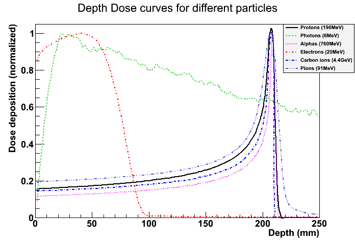
Figure 1: Deposited dose plotted as function of depth in tissue. Image generated using Geant4, and all curves are normalized.
The reason why α radiation has been neglected in favor of X-rays is that they have a very limited range: when created in atomic decay a sheet of paper is enough to stop them. This means they are not suited for treatment or imaging. Electrons have the problem that they scatter enormously in tissue: they are almost 2000 times lighter than protons, and even moreso than heavier ions (Hale, None). It is therefore unlikely that they will be useful for imaging. Artificially accelerated electrons can have a higher energy and more penetrating power, and have been used for superficial treatment. Electron accelerators on a medical scale can reach up to a few tens of MeV (Hoekstra et al., 1987), at which energy they may reach a depth of about 10cm in tissue, still not quite enough to be useful for all kinds of treatments. The NIST tables (National Institute of Standards and Technology, 2011) show that to reach a depth of 20cm, electrons require an energy of about a GeV. Above a few tens of MeV energy losses due to synchrotron radiation dominate, making acceleration to higher energies inefficient. Two modern electron accelerators, ALBA and CEBAF attain energies of 3 and 6 GeV respectively, requiring impractically large accelerators for a hospital setup. The former has a synchrotron ring of 270m in circumference, while the latter has two linear accelerators of 1400m coupled by two half rings. All things considered, electron therapy is not practical except for superficial treatment.
The therapeutic use of alphas has not yet become common due to prohibitive costs of manmade accelerators necessary to penetrate the body. As can be gleaned from figure 1, at energies of about 200MeV they can penetrate the human body. The depth that can be reached is a function of beam energy, which becomes unpractical only at energies well above what is required in the medical context. With the advent of hadron accelerators since the mid-twentieth century their application in medicine has been studied. Helium is rather sparse, so usually protons or carbon ions are accelerated. The general term for this category is now hadron therapy, since any hadron can be accelerated with such a machine. The depth-dose curve shows a clear and sharp peak, the Bragg-peak, which means dose is delivered to a specific region as opposed to the much more even distribution of X-rays. Because physics research have made cost and size of accelerators come down, and because of the desirable depth-dose curve of hadrons, interest has steadily increased since the first treatment of patients in 1954 (Schardt and Elsässer, 2010). In 1968 the first proton-image was made by Koehler (1968), showing that there is potential for imaging using hadrons too.
3.2. Particle Beams for Hadron Therapy
An accelerator uses an electric field to accelerate charged particles (by either attraction or repulsion). Magnetic fields are used to keep the particle in orbit, in modern synchrotrons usually a circular one. As particle speed increases, confinement and control of the particles becomes very difficult: that is why an enormous engineering effort is necessary to build stable and robust particle accelerators. Of course physics research, accelerator development and hadron beam therapy developed hand in hand, taking advantage of each new development in one of the disciplines. Only in the last few decades have accelerators specifically built for medicine been feasible, and it is not hard to imagine that size and cost are deciding factors. Schardt and Elsässer (2010), Amaldi and Braccini (2011), Schippers and Lomax (2011) provide excellent overviews of the world-wide state of affairs of medical accelerators, and Schardt and Elsässer (2010) mention for example a 20 ton accelerator being installed in two hospitals late 2010. This indicates development is at full speed. Two types of accelerators are found in medical setups: the synchrotron and the cyclotron. The first type is seen in most designs intended for carbon therapy, while the second is found in most proton facilities, as well as in most standalone devices presented by companies who focus on downsizing the accelerator. While the synchrotron accelerates particles in batches, the cyclotron operates continually and gives off a current of particles.
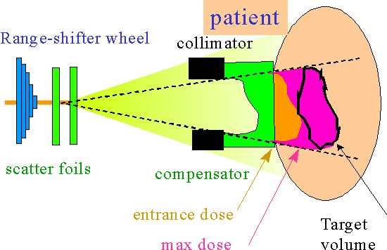
Figure 2: An illustration of the typical components used in passive beam shaping. The compensator or bolus shapes the beam into the tumor shape.
A treatment plan is the term for the best approach to irradiating the tumor, and is constructed on a case-by-case basis in the hospital. At the moment of discovery, the tumor will typically have a size multiple centimeters in all 3 dimensions, and be located under layers of other tissues. Each volume element, or voxel, has its specific coordinates and requires a specific dose. The treatment plan depends therefore on the beam shape, beam energy, dimensions of the tumor and the sensitivity of surrounding tissues. The incident angle of the beam line itself can be controlled: most hospital setups feature a gantry, which is a name for the installation that can rotate the beam nozzle around the patient. Usually the table on which the patient is laid down can move. With the beam energy we can control the depth of the Bragg-peak, and by aiming the beam we control the other 2 dimensions. There are generally two ways the shape (the cross section of the beam) is controlled: passive beam shaping or spot scanning (Schardt and Elsässer, 2010, Amaldi and Braccini, 2011, Schippers and Lomax, 2011).
- Passive beam shaping is a method where the beam is attenuated with passive methods (fig. 2). Although it has many pieces, once set there is little or no interaction required for the beam to deliver the proper dose to the targeted areas of the body. The beam is first slightly scattered after which structures such as collimators and attenuators shape the beam into a uniform 2D distributed flux, so that a certain area can be uniformly irradiated at once. Then there is a patient specific mold, a bolus, that shapes the range such that the Bragg-peak is delivered at the proper depth. Some atomically light plastics are used to alter the range and not scatter as much as heavier materials. To alter the penetration depth of the beam, range shifters may be used. This is a wheel with plates of varying thickness which can be spun in the beamline, thereby altering the range of the protons by decelerating them, depending on the thickness of the wheel at that point.
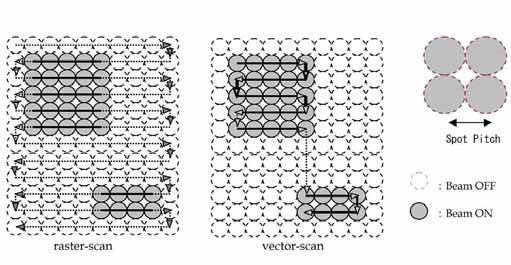
Figure 3: On the left raster scanning and on the right vector scanning. Vector scanning can be seen as an optimization of raster scanning, where some speed is gained in favor of a slightly more complicated treatment plan.
- Spot scanning (Staab et al., 2011), or raster scanning, moves the beam spot by a modulating a magnetic field at the accelerator nozzle. The energy can be controlled by altering the accelerator energy or using a ranger shifter wheel between the accelerator nozzle and the patient. This scanning may occur in a raster-like fashion, as found in old Cathode Ray Tube monitors, or by scanning only over the lateral projection of the tumor, sometimes referred to as vector scanning (fig. 3).
These aspects have their respective advantages and disadvantages. Putting materials in the beam line decreases particle rate and increases scattering, reducing the potential resolution. Moving objects in and out of the beam requires the beam to be off and is therefore dead time. Modulating the beam energy requires time as well, so the speed at which this can change has consequences for the possible treatment plans. Because the Bragg-peak is so precise, the patient is usually fixed to the table to within a few millimeters. This is very uncomfortable, so a treatment must not last too long. Parts within the body move as well: blood flows, lungs move while breathing and bowels contract and expand. For example, the HIT facility in Heidelberg takes breathing into account by switching the beam off every cycle, for a certain period of time, to ensure accuracy. Of course, this again costs time, because the amount of dose that needs to be deposited doesn’t change. In other words, dose delivery is a major point of attention. Other strategies of motion compensation or mediation are being researched (Schardt and Elsässer, 2010).
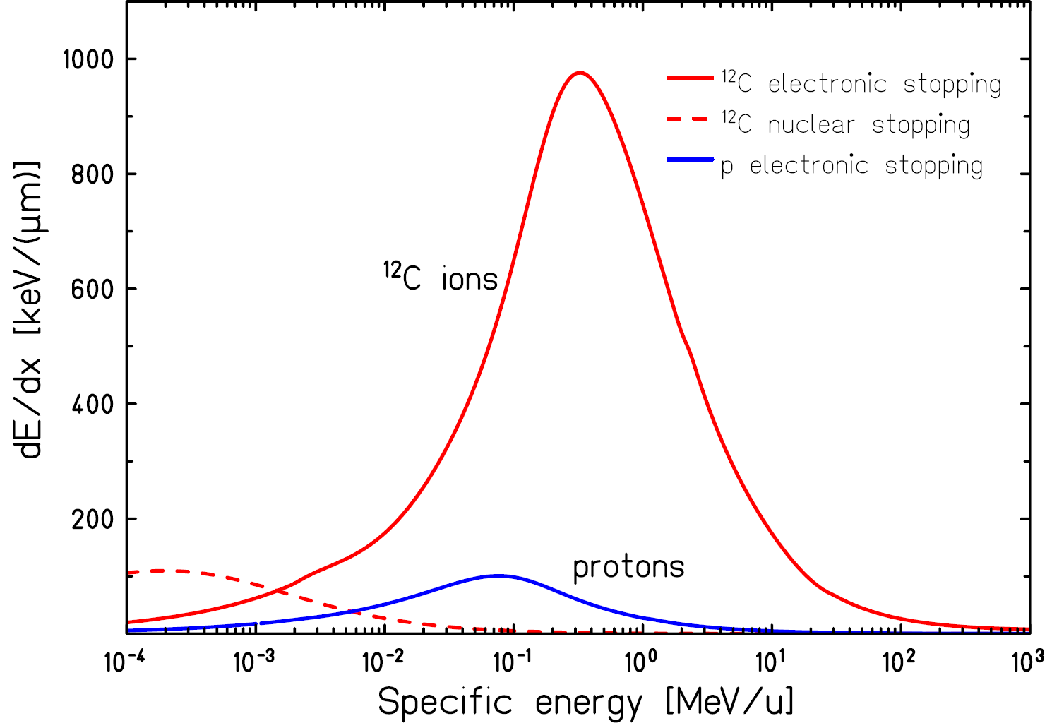
Figure 4: dE/dx curve, or stopping power, for protons and carbon ions as function of initial energy. Assuming the initial energy is in the range of a few 100MeV, it is clear how the Bragg-peak comes about: the deceleration accelerates itself Schardt and Elsässer (2010).
Then there are the details of the interaction of hadrons with matter, not only collimators and range shifters, but also the body itself and also the air between the parts. The Bethe-Bloch equation tells us how much energy is lost per unit distance, and this curve is plotted for protons and carbon ions in figure 4. The deceleration accelerates itself, which is why most energy is lost over a very short distance (fig. 1). Wilson (1946), Schardt and Elsässer (2010) list the following important effects of hadrons in matter:
Range straggling.
The hadron loses energy by ionizing other particles in its path. This is a statistical process, and therefore introduces smearing to the Bragg peak. The Bragg-peak size for protons is about 1% of their range in a certain material. Considering the dimensions of a tumor, this is a beneficial effect. The whole tumor needs to be irradiated, and range straggling increases the minimum voxel size and thereby speeds up treatment. Imagine that pin-pricking the tumor is precise, but takes a long time if the whole tumor volume needs to be treated.
Multiple Coulomb scattering.
Multiple Coulomb scattering, or Elastic Coulomb scattering, describes interactions that cause many small angle scatterings of the hadron, which in turn cause a spread of the beam in the transverse plane. Using equation (1) from Molière’s theory, where
 is the traversed depth through a certain material and
  the radiation length of that material, U. Weber of Rhön-Klinikum has constructed figure 5. For the case of the November testrun, assuming a proton with 150MeV, this translates to a angular spread for 3m of air in
  , for 20cm of water in
  , for a GridPix (2x10μm Cu and 2x50μm PCB) in
  and for 5cm of aluminium in .
(1)
![\theta_0 = \frac{13.6MeV}{\beta c p} \: z \: \sqrt{x / X_0} \: [1 + 0.038 \: ln(x / X_0)]](../images/math/432ca5d2f50c8c20743c24c35ffd7e664ef6bbc3.png)
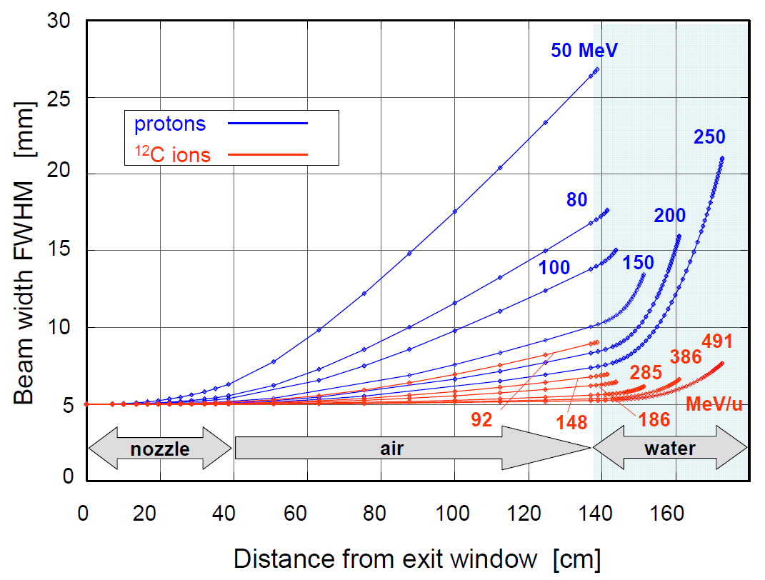
Figure 5: The beam spread for different types of hadrons at different energies are shown for a certain beam and a certain setup. The trend visible is that particles with higher energies and/or heavier ions provide a smaller spot size. This effect in combination with the former two results in a spread of the Bragg peak over a small volume, which is a few millimeters in depth (figure 1) a bit more in the transverse plane. Note that the distance from the exit window need not be this large, and the relative performance of the (lower energy) protons can be increased.
Nuclear fragmentation.
Target nuclei and the accelerated ion itself may break up after a head on collision. A broken up ion translates to various new lighter nuclei traveling at a similar speed to the parent ion. Lighter ions have a longer range (see figure 4) and therefore contribute to a tail after the Bragg-peak of the parent ion. Heavier ions tend to break up into heavier parts, which in turn can break up again. Figure 6 shows how for
 this results in a forwardly smeared depth-dose distribution. While usually seen as a disadvantage, Kraft (2000) describes it in the case of carbon ions as a potential advantage: typically beta emmitting
  and
and  are produced that could be used for direct verification with a PET scanner. Because protons can not break up, they don’t suffer from nuclear fragments and the associated downsides. Amaldi and Braccini (2011) argue however that lighter nuclei, such as He, Li and B, have a sharper distal edge to the Bragg-peak and suffer less from lateral scattering because of the increased mass.
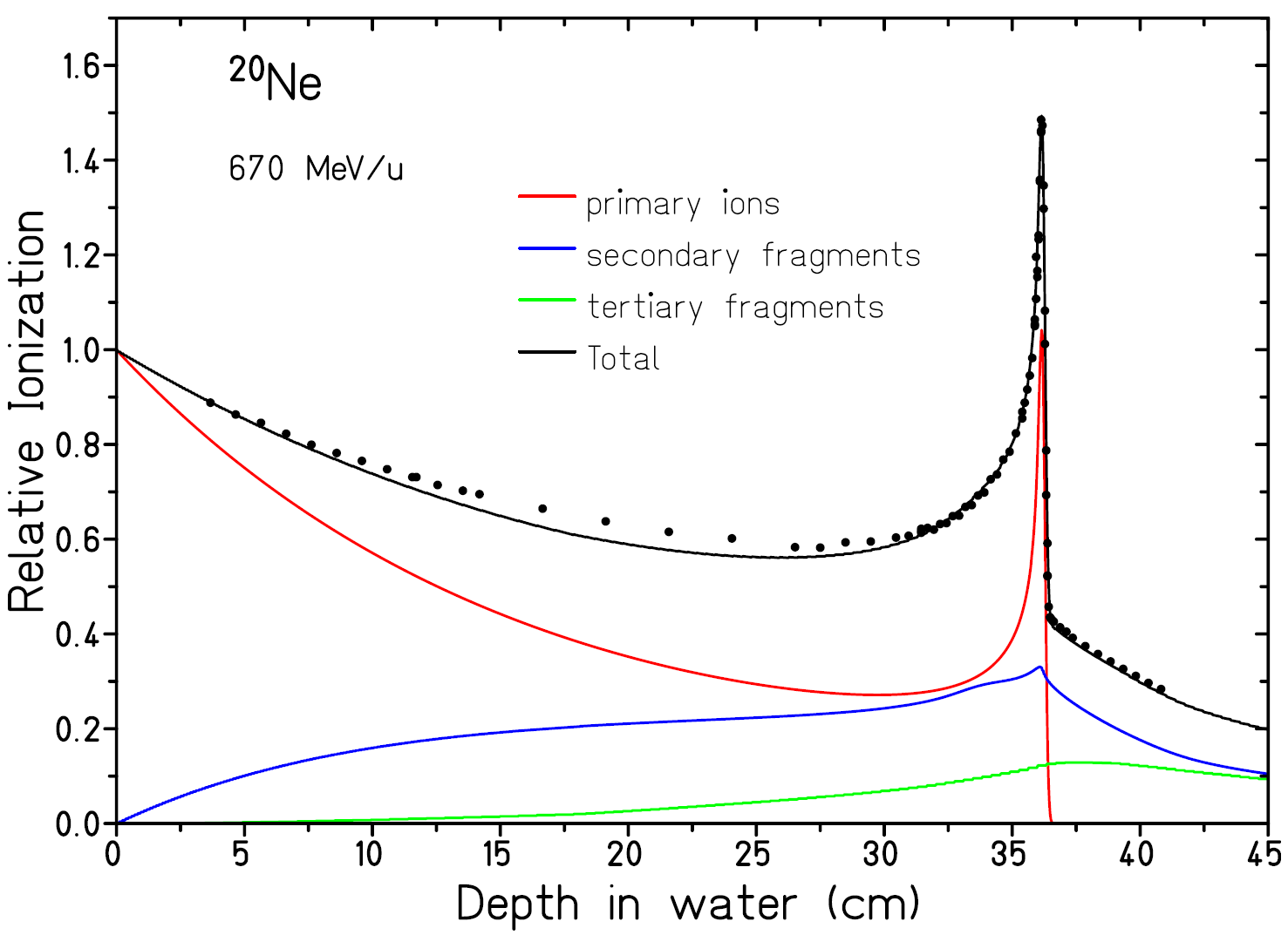
Figure 6: Dose curve for 670 MeV/u
ions in water measured at GSI and calculated contributions of primary ions, secondary and tertiary fragments. Image courtesy of Schardt and Elsässer (2010).Neutron dose.
When protons and host nuclei collide, neutrons may be produced. They keep the speed and direction of the incident proton. Passive beam shaping produces more neutrons than an active beam shapers. Fast neutrons seem to have a small contribution (<1%) to the effective dose (Gunzert-Marx et al., 2008). Neutrons do have a higher RBE than protons, and they are linked to induced secondary cancers. Brenner and Hall (2008) argue that since most neutrons are created in passive beam shaping objects, any adverse effect is easily remedied by using better accelerator designs and active scanning techniques.
 -rays.
J.J. Thomson noticed that the recoil of target nuclei can cause secondary ionisation. He referred to this radiation as
-rays, in the spirit of the other three types known at the time. These -rays, electrons, have a typical energy in the range 10 to 500 eV, and don’t travel more than a few millimeters. The number of such -rays depends greatly on the particle beam species. It is well known that heavier particles have a bigger effect on target nuclei and therefore generate much more -rays than protons (figure 7). The primary ions also produce -rays directly. These -rays have a great disruptive power by directly or indirectly causing a double strand break in DNA. The -rays generate many free radicals that increase the double strand breaking tremendously (Schardt and Elsässer, 2010). In dose calculation the effect of the free radicals is often modelled as a multiplication factor in the radial dose distribution, which in turn relates damage to distance from Bragg peak (Elsässer et al., 2007). Tumorous tissue has less regenerative capacity than healthy tissue, because cell division is increased and that is when radiation sensitivity is the highest. Slightly mitigating the positive effect is that normal tissue is more sensitive to free radicals than tumors, due to the typically low concentrations of oxygen in tumors. A double strand break often results in the host cell being unable to repair itself and die, which is why this effect is an important consideration.
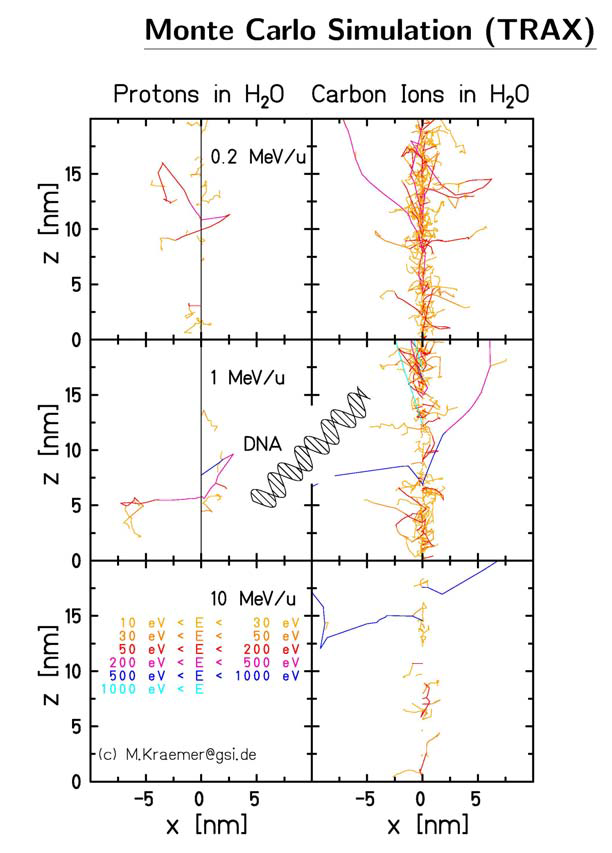
Figure 7: Carbon ions and protons have a very different ionisation potential along their paths. Because carbon has much densely ionized clusters, the disrupted volume reaches the dimensions of a DNA strand, which then can be broken clean in two, greatly disabling the host cancer cells ability to recuperate. Image courtesy of Dieter Schardt.
Another drawback of hadron therapy is shown in figure 8. The Bragg-peak delivers its highest concentration of damage in a volume of a few millimeters cubed. A tumor that manages to be discovered is typically quite a bit larger than that. In a treatment plan the volume of the tumor is subdivided in voxels of about the size of the Bragg-peak volume of damage. The beam is moved and altered to as to place a peak in all voxels. The unfortunate side effect is that the radiation in tissue before the tumor is a sum of many curves. Compared to the exponential decay of an X-ray curve, this is still an improvement.
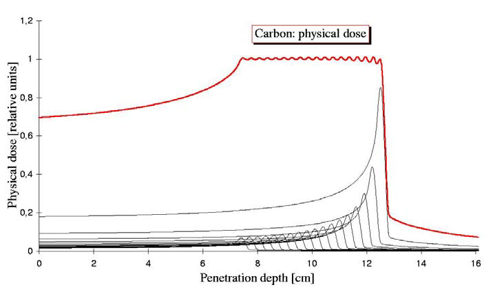
Figure 8: In order to irradiate over the tumor volume, multiple hadron energies are summed. This has the unfortunate side effect of an increased dose before the tumor, to healthy tissue. Image courtesy of Dieter Schardt.
Species of hadrons considered for medical purposes are types such as H, He, Li, Be, C and Ne, of which the proton is by far the most used. The upside to heavier hadrons is the increased RBE compared to protons, predominantly due to increased ionization (-rays). The downside is fragmentation: the debris stops before or after the Bragg peak and makes the dose deposition less accurate. Target cells can be however killed only once, and ions heavier than oxygen create more damage than what is required. Some research has been done on pion radiation (Wisser, 2004, Goodman et al., 1990) that concluded that the performance has no clear advantages nor disadvantages compared to protons or carbon ions. Even less research has been performed on antiprotons which is summarized by Amaldi and Kraft (2005) as having ‘non-obvious advantages’. Both have one clear disadvantage: the production of these exotic particles is costly compared to normal matter. Without going into detail, the biological effects of different types and energies of particles are rated with an RBE rating, which converts deposited dose into effective dose. This rating depends on many factors, and is used to quantify the specific characteristics of a certain type of radiation into a single number that can be easily used in treatment plans.
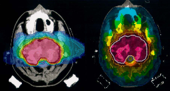
Figure 9: On the left a carbon irradiation using 2 fields. On the right a treatment plan for an X-ray irradiation using 9 fields. Using fewer fields the carbon plan manages a much more confined dose delivery. Note that in addition the carbon plan deposits almost no dose in the optical nerves, which is a well known type of tissue extremely sensitive to radiation. Source: Amaldi and Kraft (2005).
Taking these considerations into account, on paper hadron therapy compares favorably to X-ray therapy. A comparison of treatment plans may be seen in figure 9. The advantage of less dose before the tumor is also used to reduce the number of directions the beam is pointed. Changing beam position (or patient position) consumes time, so this time is saved. Two excellent papers that cover the current state of affairs in much more detail are Rossi (2011) and Schardt and Elsässer (2010). The former includes the specific details of the construction of a facility, while the latter mostly deals with technical and biological considerations.
3.3. Imaging and Computed Tomography
Previously, we saw that imaging and treatment have distinct goals and distinct demands on the type of radiation used. We’ve also established that the X-ray is currently the default modality for both imaging and treatment. In treatment, as well as diagnosis, an accurate view of the patients internals is required, and this view is obtained with  CT. This method makes use of the fact that different tissues have different X-rays absorbtion coefficients. Imaging is a collective term for any and all types of images, including simple ‘photographs’. A CT scan composites multiple flat images into a 3D model, in which certain tissues are identified and optionally highlighted and viewed in the direction that is desired (figure 10).
Using the fact that the intensity loss of the X-ray beam can be calculated from the known intensity of the beam and the intensity recorded in the camera, an image of (a region of) the body can be created by taking such pictures from all around the patient. Godfrey Hounsfield received the Nobel Prize in 1979 for having this idea, and the scale used in radiology to measure the radiodensity is referred to as the Hounsfield-scale with unit HU. Equation (2) shows how a HU relates to radiodensity (expressed as  ) which in turn relates to the energy loss of the X-rays by way of Lambert-Beer’s law.
(2)![HU = [[\mu(X) - \mu(water)]/\mu(water)]* 1000](../images/math/9ab11f946f4486aab1ad4689fabd82417fd8a4bd.png)
To give a feel for these numbers: air is -1000, bone +700, and fat, water, blood and muscle are respectively -84, 0, +30 to +45, and +40. The major drawback of γCT is that many types of soft tissue, of which the body is primarily composed, have very similar Hounsfield values, and therefore are hard to distinguish. This distinction is not only hard to make visually, but also when creating the best treatment program. Sparing the surrounding healthy tissue is difficult when the physical limits of the tumor are not well known. The radiodensity for hadrons is usually expressed as stopping power. Hanson et al. (1981) wrote a pioneering comparison of the two modalities, and he expresses radiodensity in terms of linear stopping power compared to water for protons and the X-ray attenuation coefficient for the γ modality. He also shows that for a given contract ratio, protons incur an order of magnitude lower dose on the body while imaging, compared to X-rays.
In the introduction to this chapter the use of tracers in PET scans was briefly mentioned. The imprecision of γCT is typically mitigated with tracers as well; high contrast materials that are administered to the region of interest. The disadvantage of tracers is that they require time and effort to administer, it is not trivial to place them precisely at the region of interest, and that metabolic processes in the body move and disperse the tracer. Particle beams introduce two alternative options: In-Beam PET and Hadron CT.
In-Beam PET.
Particle irradiation can introduce
sources in the body. These can be produced in fragmentation of particles due to the beam, or by using emitters as the beam particle. Amaldi and Braccini (2011), Schardt and Elsässer (2010) mention that at GSI and  were used to this extent. The article mentions further that the detection of ‘prompt’ gammas is particularly interesting. These prompt gammas are created in the interaction of the incoming particle and bodily material, and originate therefore certainly at a point of damage. If the emitter is the incident particle, or a secondary emitter generated by an interaction, there is a certain decay time, which means the particle will have moved due to metabolic processes and thereby decrease precision. The main benefit is therefore that there is no separate tracer needed, and that imaging is a ‘free’ bonus to therapy. Imaging is perhaps an overstatement: this method makes the irradiated volumes directly visible and can be used as a check of a treatment plan but not for diagnosis. The downside is that the emissions of photons have no preferred direction, so a detector should enclose all angles, which in turn is expensive and impractical. If the detector is in another room, prompt emissions are not detectable at all. The decay times of and are respectively about 20 and 2 minutes, which may be longer than the time it takes to move the patient to the imaging room. An extra complication is that the treatment itself has a duration of this order, which means that there will be a significant difference in activity between regions irradiated at the start and the end of the treatment.
Hadron CT.
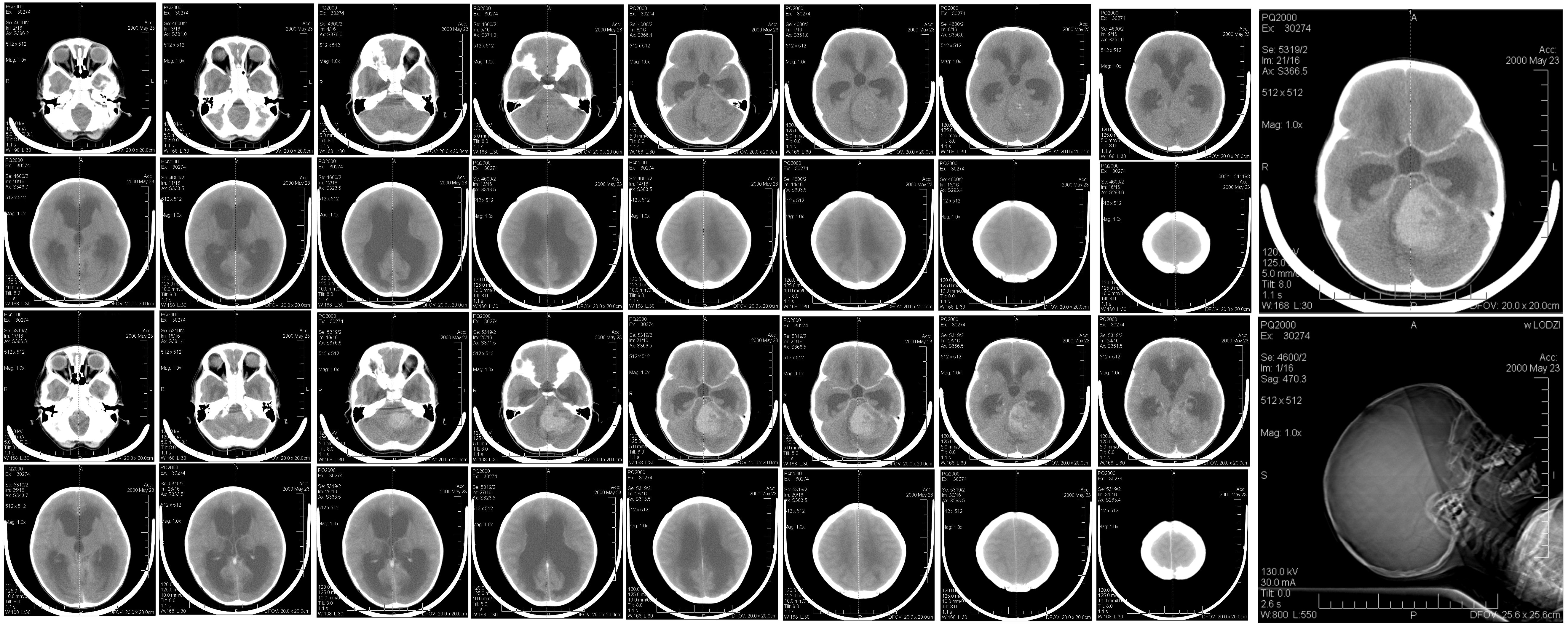
The hadrons themselves could be tracked and absorbed in order to create an image. Using energies higher than for therapy, placing the Bragg peak behind the body, the ionizing damage could be minimized further. Apart from sparing tissue compared to X-ray irradiation (figure 1), there is a second benefit to hadrons for imaging: an increased density resolution in comparison to X-rays. Figure 11 shows how Ryu et al. (2008) makes that clearly visible. More contrast is seen between the different types of material, and, using different calibration curves, the contrast may be adjusted as a doctor sees fit. Also visible is the difference in sharpness: because protons scatter much more than photons, the precision in the plane perpendicular to the beam is lower. For imaging, it seems hadron-CT could augment the γCT in the depth dimension. Moreover, conversion of radiodensity of the different modalities (γCT Hounsfield numbers versus hadron stopping powers) is a relatively imprecise method, introducing an error of up to 3% (Penfold et al., 2009). Using hadron data sidesteps this problem completely. Producing usable hadron images therefore is desirable even if they will not be used for diagnosis.
Figure 11: The top two images show proton beam images for two different dose-depth calibration curves. The bottom image shows a standard X-ray scan. Note the missing features in the X-ray image and the difference in sharpness. Image courtesy of Ryu et al. (2008).
Going from simple 2D projections to a fully reconstructed CT scan is a nontrivial matter, so let us start with the simple case of the 2D image. For every pixel one residual intensity value is measured, and therefore the opacity of the body is summed over all tissue behind that pixel. The spatial distribution in the depth direction is therefore lost. An accurate 3D model reconstruction would aid in the establishment of opacity, and thus radiodensity, for each volume element. The radiodensity is tissue-specific, so full knowledge of spatial distribution in the depth direction would be reconstructed and the structure of the the patients body would be known. With conventional X-ray imaging, the common geometry in γCT is a camera rotating about an axis parallel to the length of the patient. A series of 1D line integrals are obtained by moving the camera around the patient. As the camera moves along the body, new sets of 1D line integrals are obtained, each corresponding to a slice of tissue: tomography. The line integral of the absorption is now known for many different positions and angles, and the reconstruction software reconstructs for each voxel in a slice the local absorption coefficient, resulting in a 2D image: computed tomography. These typical 2D 30cm squared images are what most doctors are used to. As available computational power increased, the 3D reconstruction of the body in the detection volume became possible. For hadron CT, or pCT, as protons are the most commonly used hadrons, rotating the camera and the beam around the patient requires an expensive gantry. An extra constraint for pCT could therefore be that algorithms work well without a gantry; it can cope with images from a reduced number of angles. One could consider changing the position of the patient table instead of the gantry.
3.4. Modalities in Medicine
This chapter has given the reader a flavor of the field of hadron treatment and imaging. To briefly summarize the benefits of hadrons as an imaging modality is that it is sensitive to structure in the dimension that γCT is not sensitive, so a potential combination of the two seems promising. Secondly, an inherent advantage for hadron imaging is less ionizing damage incurred on the body. Lastly, it is preferable to image in the same modality as the treatment to sidestep radiodensity conversions for an increased accuracy for dose deposition. The following table is supposed to summarize the advantages and disadvantages of the different modalities.
| Modality | Ease of use | Imaging | Treatment |
|---|---|---|---|
| γ | Cheap to generate | Easy to record | Can penetrate whole body |
| β | Cheap to generate | Limited range Extreme scattering because of atomic electrons |
Limited range |
| Hadron | Expensive to generate | Hard to record Good density resolution |
Accuracy of dose deposition at specific depth |
| Neutron | – | – | Ill defined dose distribution |
| Pion | Very expensive to generate | – | Instability with undesirable decay products |